- All
- Product Name
- Product Keyword
- Product Model
- Product Summary
- Product Description
- Multi Field Search
Views: 20 Author: Site Editor Publish Time: 2023-07-10 Origin: Site
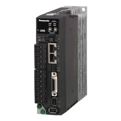
Realtime Express (RTEX)
Advanced Network to realize high-precise real-time performance for Servo Control

<Caution>
Please select the appropriate tightening torque for the product's mounting screws, taking into consideration the strength of the screws used and the material to which they are attached, to avoid loosening or damage.
Example) When tightening steel screws (M5) to steel, 2.7 N•m to 3.3 N•m.
| Driver | Applicable motor | Voltage specification (V) *1 | Rated output (W) | Power supply capacity (at rated load) (kVA) | Circuit breaker (Rated current) (A) | Short circuit protection element (Fuse) (A) | Noise filte (Single Phase/Three Phase) | Ferrite core | Electromagnetic contactor (A) *2 | Conductor thickness for main circuit Withstand voltage | Terminal block crimp terminal for main circuit *3 | Wire thickness for control power supply | Terminal block crimp terminal for control power supply | Motor wire thickness Withstand voltage *6 | Terminal block crimp terminal for motor *4 | Brake wire thickness Withstand voltage *6 | |
|---|---|---|---|---|---|---|---|---|---|---|---|---|---|---|---|---|---|
| Main circuit power input line | Control circuit power input line | ||||||||||||||||
| MADN | MSMG MHMG | Single Phase 100 | 50 | Approx.0.4 | 15 | 10 | 1 | DV0P4170 (Single phase only) | DV0P1460 | 20 (3P+1a) | 2.0 mm2/ AWG14 300 VAC or more | Connecting to a dedicated connector | 2.0 mm2/ AWG14 300 VAC or more | Connecting to a dedicated connector | 0.75 mm2/ AWG18 to 2.0 mm2/ AWG14 300 VAC or more | Connecting to a dedicated connector | 0.3 mm2/ AWG22 to 0.75 mm2/ AWG18 100 VAC or more |
| 100 | |||||||||||||||||
| MBDN | 200 | Approx.0.5 | |||||||||||||||
| MCDN | 400 | Approx.0.9 | 20 | DV0PM20042 | |||||||||||||
| MADN | Single Phase/Three Phase 200 | 50 | Approx.0.5 | 10 | DV0P4170 (Single phase only))/ DV0PM20042 | ||||||||||||
| 100 | |||||||||||||||||
| 200 | Approx.0.6 | ||||||||||||||||
| MBDN | 400 | Approx.1.0 | |||||||||||||||
| MCDN | 750 | Approx.1.9 | 20 | DV0PM20042 | |||||||||||||
| MHMG MDMG MGMG MHMG | 850 | Approx.2.4 | DV0P4220 | 32 (3P+1a) | |||||||||||||
| 1000 | |||||||||||||||||
| MDDN *5 | 1000 | 35 | |||||||||||||||
| 1300 | Approx.2.9 | ||||||||||||||||
| 1500 | |||||||||||||||||
*1 For single phase/three phase 200 V common specifications, select peripheral equipment according to the power supply used.
*2 The electromagnetic contactor used for the external dynamic brake resistor should have the same rating as the electromagnetic contactor used for the main circuit.
*3 Use the same crimp terminal for the ground screw as the crimp terminal for the main circuit terminal block.
*4 Make sure that the thickness of the ground wire and the external dynamic brake resistor wire are the same or larger than the motor wire.
*5 For UL certification, in the case of a single phase power supply, please use a clamp meter that can measure the effective value current and derate the input effective current to 12A or less.
*6 Applicable wire size varies depending on the motor model number. Please check the instruction manual or specifications document for the applicable wire size for each motor model number.
* Specifications are subject to change due to improvements, etc. Please be sure to obtain the latest information when using these products.
To comply with EU directives/UK standards, be sure to connect an IEC standard and UL certified (LISTED, marked) molded circuit breaker between the power supply and the noise filter.
Make sure that the short-circuit current of the power supply you use is less than 5000 Arms symmetrical current when the product’s maximum input voltage is less than that. If the short-circuit current of the power supply exceeds this, install a currentlimiting device (current-limiting fuse, current-limiting breaker, transformer, etc.) to limit the short-circuit current.
<Caution>
• Select a molded circuit breaker and noise filter with a capacity commensurate with the power supply capacity (taking load conditions into consideration).
• Use copper conductor wires with a temperature rating of 75 °C or higher for wiring.
• For frames A to D, use the included dedicated connectors. In that case, keep the length of the stripped wire between 8 mm and 9 mm.
| Driver external frame symbol | Ground screw | Connector to upper controller (X4) | ||
|---|---|---|---|---|
| Call | Tightening torque (N・m) Note)1 | Call | Tightening torque (N・m) Note)1 | |
| MADN, MBDN, MCDN, MDDN | M4 | 0.7 to 0.8 | M2.6 | 0.2±0.05 |
Note)1
<Caution>
• Exceeding the maximum tightening torque may cause damage.
• Do not turn on the power while the terminal block screws are loose.
• Turning the power on while the screws are loose may cause smoke or fire.
<Remarks>
• Check the tightening torque periodically once a year for looseness.

